Compact Mobile Battle Robot
As part of a team of four engineers (Solomon Gonzalez, Pyo Lim, Cole Nagata, and myself), we designed and built a compact mobile robot for a competitive robot battle arena game. The competition, called RoBA (Robot Battle Arena), pitted three robots against three in head-to-head matches. Each team’s objective was to deal damage to the opposing base, capture towers, and disable enemy robots.
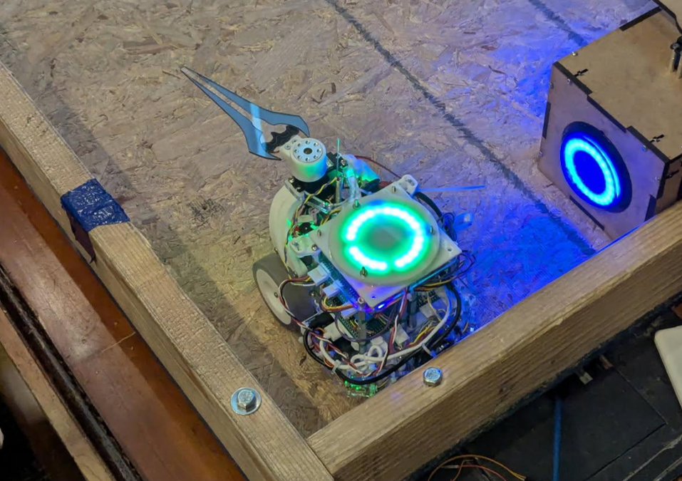
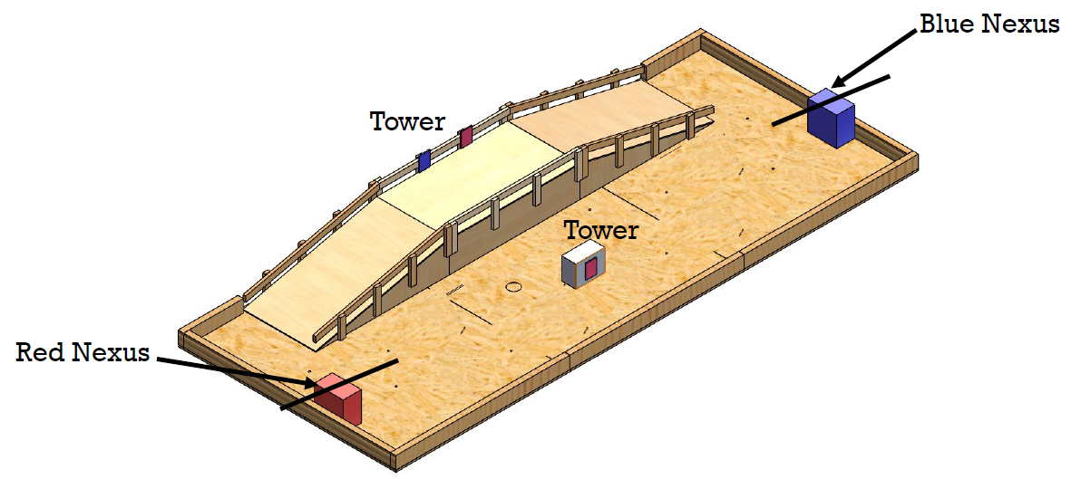
The arena featured a central ramp and multiple towers. Each team had a base, called the Nexus, that could be attacked by pressing a button mounted on it. Robots could also capture neutral towers positioned on the map by pressing their buttons. Once captured, a tower would deal continuous damage to the opposing team’s Nexus over time, making control of the arena just as important as direct attacks.
Each robot carried a “Top Hat” module provided by the competition organizers. This module tracked the robot’s health and enforced game rules:
- Robots started with a fixed amount of health points (HP).
- A physical hit, registered by a whisker switch on the Top Hat, caused the robot to lose 10 HP with a cooldown of 0.5 seconds between hits.
- Every WiFi packet sent by the robot also cost 1 HP, penalizing overuse of remote communication and forcing teams to make careful design tradeoffs.
- Health status was displayed on an LED ring, visible to referees and opponents.
Robots were eliminated when their HP reached zero. Victory was achieved either by destroying the opponent’s Nexus directly or by draining it through captured towers while keeping your own Nexus defended.
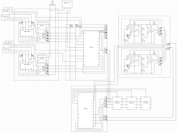
System Architecture
Our design used two cooperating ESP32-C3 microcontrollers to divide responsibilities:
- Sensor MCU (high-level planner): managed inputs from multiple sensors (Time-of-Flight distance sensors, Vive localization circuits, and the competition Top Hat health module). It made navigation and strategy decisions such as wall following or advancing toward a target.
- Motor MCU (low-level controller): executed motor control with encoder feedback, running proportional speed regulation to ensure accurate turns and straight-line driving. It also controlled the robot’s servo-driven attack arm.
The two MCUs communicated over I2C, with the Sensor MCU acting as master. This separation ensured time-critical motor actuation was unaffected by higher-level planning workloads.
Web-Based Control Interface
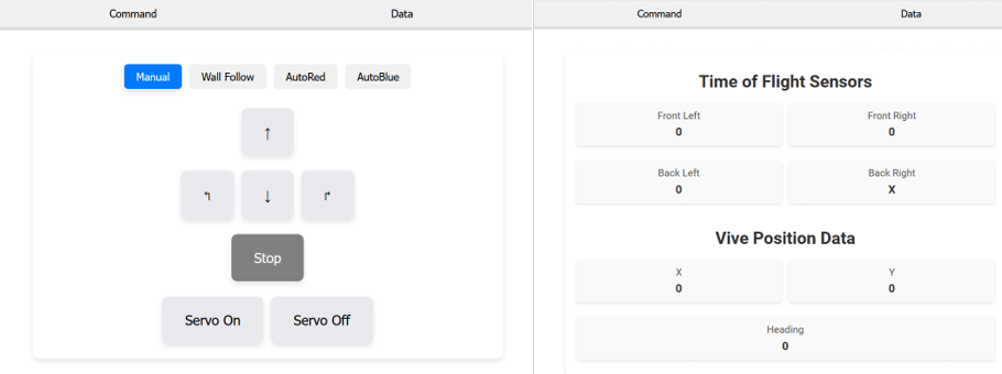
I built a simple HTML interface that the ESP32-C3 hosted directly over WiFi. This interface allowed real-time control of the robot from any connected device without needing extra software. The page featured two vertical sliders, one for each wheel, that could set speeds between full forward and full reverse.
There was also a toggle switch for enabling closed-loop control. In open-loop mode, slider values were converted directly to PWM outputs for the motors, which was useful for manual driving and testing. In closed-loop mode, encoder feedback was used with proportional control to stabilize wheel speeds, making turns and straight driving much more consistent.
This interface doubled as a debugging tool: it let us test motor drivers, confirm encoder readings, and quickly tune control parameters in the browser while the robot was running. Because it was web-based, anyone on the team could connect to the robot and operate it during development or competition.
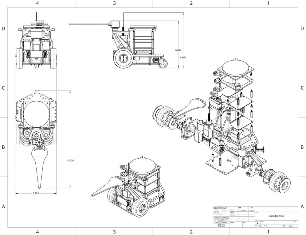
Mechanical Design
The robot measured about 8” × 4” × 5”. Two high-torque 12V worm-geared DC motors drove the rear wheels, while a front caster added stability. Wheels were custom 3D-printed using PLA for structure and elastic resin for traction and vibration damping. The chassis was laser-cut from acrylic with 3D-printed mounts for the servo, sensors, and Top Hat.
Sensors and Electronics
- 3x VL53L4CX Time-of-Flight sensors for wall-following and obstacle detection
- 2x Vive photodiode circuits for localization (though unreliable signal-to-noise limited their use in competition)
- TB67H450FNG motor drivers for efficient brushed DC motor actuation
- Power: 7.4V LiPo (boosted to 12V for motors) and a USB pack for control electronics
Electronics were organized across five perfboards (two motor drivers, two ESP32s, one for Vive circuits), stacked vertically and connected with crimped Molex wires to simplify debugging and minimize wiring noise.
Competition Performance
The robot consistently performed in autonomous wall-following mode, successfully pressing buttons and navigating around obstacles. Despite the failure of one ToF sensor and noise issues that limited the Vive system’s effectiveness, the robot remained competitive, even destroying an opponent’s Nexus during one match.
Bill of Materials (highlights)
- 2x ESP32-C3 microcontrollers
- 2x 12V worm-geared DC motors with encoders
- 2x TB67H450FNG motor drivers
- 3x VL53L4CX Time-of-Flight sensors
- 2x Vive photodiode circuits
- 7.4V LiPo battery + boost converters
- Acrylic chassis, caster wheel, 3D-printed wheels
- Total cost: roughly $167